Technical Data Sheet
max = maximum; min = minimum
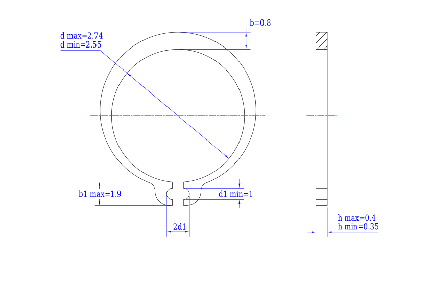
Active drawing
Retaining Rings (Shaft)
Use DIN 471 external circlip geometry as the starting point for a drawing-controlled retaining ring. Adjust shaft diameter, groove diameter, ring section, opening, material, heat treatment, surface finish, tolerances and inspection for your assembly.
Use this DIN 471 drawing generator to configure dimensions, review the technical drawing and export a custom drawing for manufacturing. Whether the specification is written as DIN 471 or DIN471, this online drawing tool covers the same Retaining Rings (Shaft) standard reference.
Define the nominal shaft and groove diameters, ring cross-section, opening clearance, material, heat treatment, finish and dimensional tolerances. Any departure from the reference standard is manufactured to the approved custom drawing.
max = maximum; min = minimum
Unit: mm
| Dimension | h/max | h/min | d/max | d/min | d1/min | b1/max |
|---|---|---|---|---|---|---|
| Φ3 | 0.4 | 0.35 | 2.74 | 2.55 | 1 | 1.9 |
| Φ4 | 0.4 | 0.35 | 3.74 | 3.55 | 1 | 2.2 |
| Φ5 | 0.6 | 0.55 | 4.74 | 4.55 | 1 | 2.5 |
| Φ6 | 0.7 | 0.65 | 5.64 | 5.45 | 1.2 | 2.7 |
| Φ7 | 0.8 | 0.75 | 6.56 | 6.32 | 1.2 | 3.1 |
| Φ8 | 0.8 | 0.75 | 7.46 | 7.22 | 1.2 | 3.2 |
| Φ9 | 1 | 0.94 | 8.46 | 8.22 | 1.2 | 3.3 |
Send the drawing with shaft and groove sizes, section, material, heat treatment, finish, quantity and inspection requirements for quotation.
Request a quote